Ever since Geometry Nodes were added to Blender I’ve been thinking of doing some tests to seek opportunities to utilize them for rigging. This morning I finally did the first one. The basic idea behind it is to create weights without painting them manually. Instead, this system would define weights using meshes as guides.
Before I continue, let me say that Geometry Nodes are new to me. If you are more experienced and have ideas on how to improve on this approach, reach out on Twitter or something and let me know so I can learn something too.
Attributes

Target – Name of the vertex group that should receive the weights.
Group 1/4 – Attribute for each vertex group on the mesh. I will get back to this in a bit.
Gizmo – Mesh that is used to generate the new weights
Falloff – Defines the length of the weights falloff.
Influence – Scales the strength of the weights that are added to the mesh
The approach I took with adding all of the object’s vertex groups by making an attribute for each of them (group 1/4) is not ideal. It is “hard coded” for each object and if a new group would be added a new property would have to be made for it. This is the first part of this solution I am not happy with. There will be one more later on.
Split points inside/outside the gizmo mesh
We can move on to the graph now and go over what is happening there. Before we can do anything with the weights, we have to somehow figure out if points are inside or outside of the gizmo mesh. I was able to find a great technique for this in one of the Entagma videos. Here are the nodes for this section:

The way we can figure out if a point is inside the gizmo mesh is to check if the point is looking at the front or back of the gizmo mesh. If it is looking at the front then it is outside, and if it is looking at the back then it is inside the mesh. Front/back in meshes is defined by normals of course.
So we need to create an arrow pointing from each point to the closest point on the gizmo mesh and then check if this arrow is pointing in the same direction as the normal or in the opposite direction. Arrows in the 3D world are Vectors. And to create a vector that goes from A to B, we subtract B from A. Which is a bit counter intuitive, I know. A-B gives us a vector pointing from B to A. Just accept it. To better visualize this, check the next image.

The white dot is a point on the mesh and the gray plane is part of the gizmo mesh. The green line represents the normal of that face on the gizmo mesh while the blue arrow is the vector that is the result of finding the closest point on the gizmo mesh and then subtracting the point position from the closest position.
If we look at the graph above, we can see the Geometry Proximity node and the Subtract node after it. And those two are doing what I described just now. Geometry Proximity gives us the closest point on the gizmo mesh and then Subtract gives us the Vector we need.
Before the normal and the resulting vector can be compared, we need a normal at this actual position, which we can get by using the Transfer Attribute node with the Normal as the input. Which gives us something like what is in this image.

Comparing if two vectors are pointing in the same direction is very easy. It is done by calculating the Dot product of the two. A dot product is a projection of one vector onto another, in practice that also means a dot product tells us how similar vectors are. And the more similar they are means they are pointing in the same direction. If two vectors are normalized, meaning the are 1 unit long, a dot product of 1.0 would mean they are pointing in the same direction and -1.0 would mean they are pointing in the opposite direction.

If you look at the last part of the graph screenshot, you can see that the last two nodes are doing this comparison. These two Comparison nodes check if the dot product is less or greater than 0. And that, gives us the separation of points inside and outside of the gizmo mesh.
Falloff
To create the falloff, we can take the points that are outside of the gizmo mesh and remap it. Which is pretty straightforward as there is already a Map Range node. Just take the Falloff attribute we created at the start and use that as the max range value. And invert To Min/Max as we want the weights closest to the gizmo to be at 1 and to gradually go to 0 at the max range. The multiply at the end makes sure this is applied only to the points outside of the gizmo mesh.

The inside and outside weights can be combined now. I added a float curve node there to show you how you could adjust the falloff as the results of previous operations will always create a linear falloff.
All of this is then multiplied by the Influence attribute to scale it up or down.

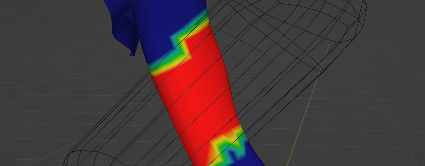
Normalize weights
At this point you could add combine this with the original weights that are on the mesh and call it a day. But, that will not produce normalized weights. Instead, lets make sure we create a normalized result. The weight adjustments happen in this part of the graph:

Remember how at the start I said there is one more part of this experiment that I am not happy with? Well this is it. This is again “hard coded”. Meaning we can’t just create more vertex groups on the mesh and expect this graph to take it into the calculation. It would have to manually be added the same way the four groups are managed in the screenshot above. For the sake of the experiment, lets say we only need four vertex groups and continue.
On to the normalization now. We want to normalize the old weights, and the new weights should come in as they are. In other words, if total weights should add up to 1.0 then we can subtract the new weights from that and the rest is what the old weights should add up to.
If you check the graph screenshot above, that is what those node do. At the bottom you can see new weights subtracted from 1.0. The results of that get divided by the sum of all old weights. The result of this is a factor by which the individual weight groups can be scaled. So if the sum of old weights was 1.0 and the nodes are taking 0.4, the new sum of old weights should be 0.6. 0.6 divided by 1.0 is 0.6. Here is another example. If the old weights were not normalized and the sum of them was 0.4, and the strength of new weights is 0.2. 1.0 – 0.2 is 0.8, and 0.8 divided by the original weight sum of 0.4 equals 2. Old weights multiplied by 2 will give us a normalized result as 0.4*2 is 0.8 plus the 0.2 added by the new weights equals exactly 1.0.
Applying the weights
We are almost there. What is left to do is to apply these adjusted values to the mesh. Then we add the new weights to the target group and apply that to the mesh as well.


Hopefully this will inspire you to play around with the setup and take it further. A demo file can be downloaded by pressing the button below. Thank you for reading.
File download
Here is a file that contains the final Geometry Nodes setup applied to an arm.
Cheers.